基本信息汇总
Bandgap的数据
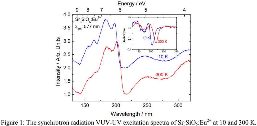
(1) Jorma Hölsä基于Sr3SiO5:Eu2+的VUV-UV SR激发光谱,认为VB到CB的激发对应于200多一点nm的激发峰,这个峰的位置随着温度的升高而红移,所对应的的估算的bandgap大约在5.96 eV (10 K下为6.14 eV)。来自文献[Yellow Persistent Luminescence of the Sr3SiO5:Eu2+,R3+ Materials ]。注意这里是光学带隙,电学带隙为5.96*1.08 = 6.44 eV
(2) 在[Dorenbos-PCCP-2015]中,测到的VB to CB的峰在207 nm,考虑激子结合能,计算得到的电学带隙为6.45 eV。
(3) 用同样的方法,在[夏志国-IC-2019]中,The excitation band at ∼200 nm is attributed to the host excitonic absorption, from which the host band gap is estimated to be 6.68 eV after taking into account the electron−hole binding energy of the exciton.
(4) 在文献[(Ba,Sr)3SiO5:Eu2+热稳定性-CEJ-五邑大学-2021]中,即使考虑electron-hole binding energy,计算得到的bandgap也只有6.05 eV。
VRBE(HBRE)能级图的分析

(1)在[Dorenbos-PCCP-2015]中是low temperature的结果。
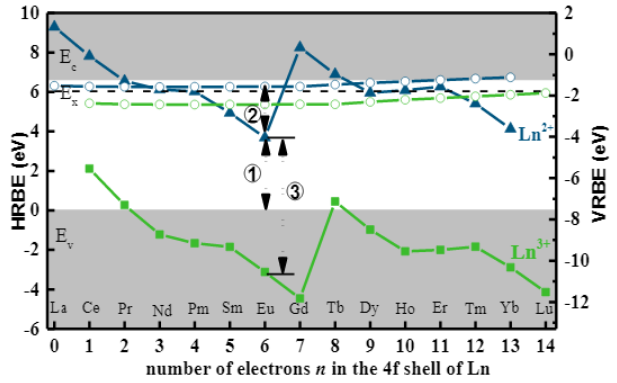
(2)上图来自[夏志国-IC-2019],作者计算的Eu2+的GS为3.69 eV,同时作者也给出了基于Dorenbos实验数据的计算结果3.96 eV (bandgap 6.45 eV),夏志国和Dorenbos的Eu2+的GS到CB底的距离分别为3.00 eV和2.49 eV。
晶体结构
- As taught by G. Blasse et al. in Philips Research Reports Vol. 23, No. 1, pp. 1-120, the host lattice in a phosphor belonging to the system Me3SiO5, where Me is either Ca, Sr, or Ba, has the crystal structure (or is related to the crystal structure) Cs3CoCl5.[Combinatorial Screening of Advanced Scintillators for High Resolution X-ray Detectors]
吸收谱的数据

(1) Undoped Sr3SiO5, whose body color is white, showed no absorption in the spectral region from near UV to visible light. [APPLIED PHYSICS LETTERS 90, 041906 2007]

(2) The relevant absorption spectrum (Fig. S4, ESI†) of SSET (双掺杂) exhibits increased absorption ability from 220 to 330 nm compared to that of SSE (单掺杂). [J. Mater. Chem. C, 2018, 6, 2978-2982]
comment: 这里是反射光谱,而不是吸收谱,另外图中红线和黑线可能标错了。
(3) All the samples have a strong absorption band in the UV region before 270 nm, which is ascribed to the matrix absorption. [J. Am. Ceram. Soc.,98[6] 1836–1841 (2015)]

(4) For Sr3SiO5: 0.03Yb3+, there are several peaks at 900–1000 nm, assigned to 4f–4f transitions of Yb3+, and two broad sub-bands at 230 and 270 nm, ascribed to the host absorption and CTB of Yb–O, respectively. Here, the assignment of the CTB of Yb–O is further supported by theoretical calculation. [Applied Physics Express 6 (2013) 082301]

(5)Nitride Phosphors and Solid-State Lighting
Eu2+掺杂的热稳定性
(1) (激发波长— 460 nm) [J. Mater. Chem. C, 2018, 6, 2978]
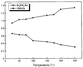 (2) (激发波长— 460 nm) Indicating that the Sr3SiO5:Eu phosphor has a more stable structure than the YAG:Ce phosphor. [Appl. Phys. Lett. 84, 1647 (2004)]

(3) Sr3-xBaxSiO5:Eu2+ (激发波长— 460 nm)
Anomalous emission enhancement is related to trapping centers in the phosphor. Thermally assisted photoionization process rather than configuration coordinate model should be responsible for Ba-sample. [Journal of Solid State Chemistry, 2015, 225: 72]
 (4) [Mater. Chem. Front., 2021, 5, 333-340]
(5) Sr2.97Si1-xAlxO5-2xNx:0.03Eu [RSC advances, 2016, 6(39): 33076]
 (6) (Sr1−xBax)2.97SiO3N4/3:0.03Eu2+ (激发波长— 460 nm) [Journal of Solid State Chemistry, 2014, 220: 172]
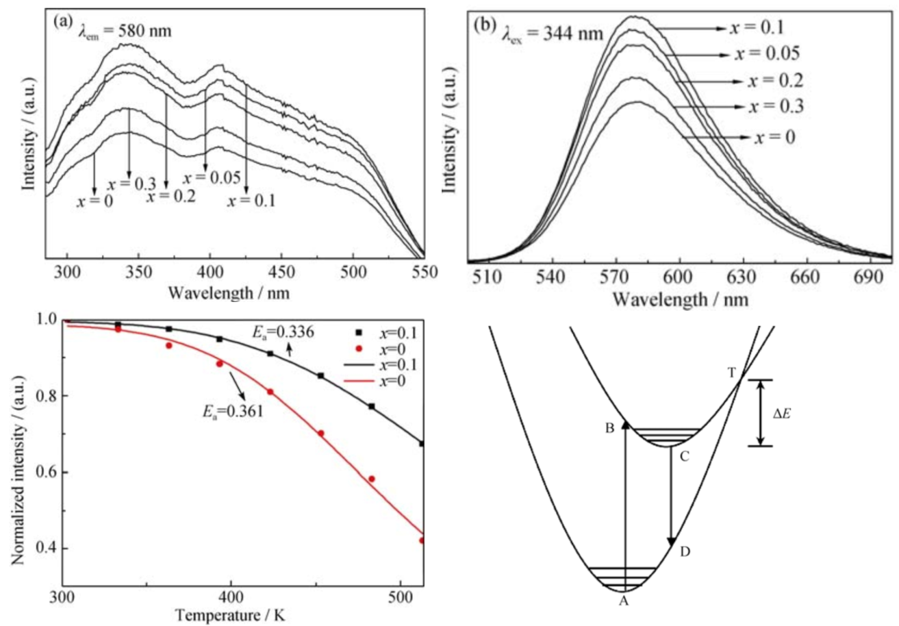
(7) 上图是Sr2.99SiO5-6xN4x:0.01Eu2+荧光粉的热稳定性图(激发波长—344 nm)。适量掺杂 N3-离子可以 提高 Sr2.99SiO5:0.01Eu2+荧光粉的热稳定性。这是因 为 Si–(O, N)键共价性比 Si–O 键要强, 掺杂 N3–离子 后可以提高荧光粉基质晶格结构的稳定性。[Si3N4 掺杂氮化对 Sr3SiO5:Eu2+荧光粉发光性能的影响]
(8)[(Ba,Sr)3SiO5:Eu2+热稳定性-CEJ-五邑大学-2021]
Eu2+ PL or Persl or PSL(OSL)文献调研
General Eu2+ PL
文献-1 Fluorescence Of Eu+2 Activated Silicates-1968
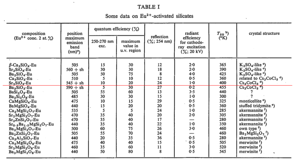

(Jieqi) : This may be the first literature that gives information about Sr3SiO5:Eu2+.
文献-2 Application of strontium silicate yellow phosphor for white light-emitting diodes-APL-2004
- PL intensity at Different Eu2+ cocentration and different excitation wavelength.
- Low quantum efficiency (68 %), which can be explained by the interaction between Eu2+ and trap/defect centers.
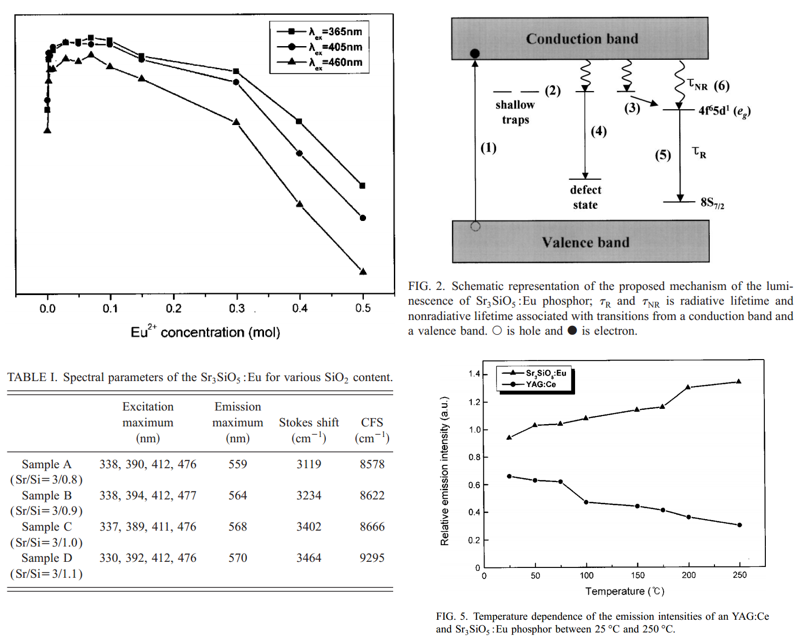
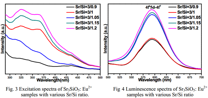
- Different Sr/Si ratio, different emission max/Stokes shift/ CFS.
The shift of the emission band to a longer wavelength occurs as the SiO2 content increases (increasing degree of covalency and CFS). -
The emission intensities of the Sr3SiO5:Eu phosphor does not decrease at all with temperature.
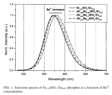
- The shifts of the emission band to longer wavelength (yellow-orange) of the Sr3SiO5:Eu yellow phosphor under the 450–470 nm excitation range have been achieved by adding the codoping element Ba2+ in the host.
- LED fabrication.
出现了Sr2SiO4的杂相:The as-prepared samples were cooled to the room temperature naturally and were orange in body color with sporadic yellow-green spots, possibly from Sr2SiO4:Eu2+, in the surface. After discarding the top layer of the nongrinded products, the interior of the samples shows uniform orange without yellow-green spots, and eventually, the uniform orange samples required were obtained.
XXX
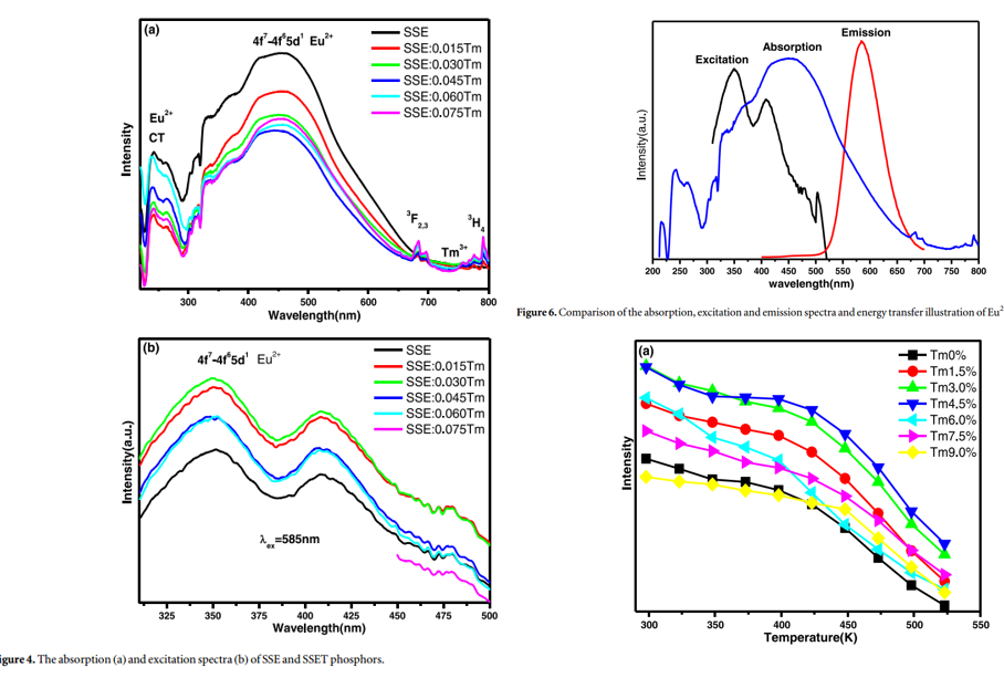
文献-5 Achieving long-term zero-thermal-quenching with the assistance of carriers from deep traps-JMCC-2018

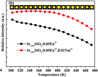
- The incorporation of Tm3+ increase thermal stability of Eu2+ emission(left figure(b)), increase TL intensity but same types of traps (TA, TB, TC, TD) in terms of trap depth under UV(left figure(d))
- 注意左侧图b,纵坐标是最大发光强度,而不是积分强度,实际上随着温度的升高,发光谱是展宽的,即如果纵坐标是积分强度,那么表现出的热稳定性会更好。
- The LPL charging spectrum(right figure(b)) is composed of a wide band ranging from 250–400 nm. This unambiguously demonstrates that only the electrons excited to a higher 4f65d1 level can be captured by shallow traps, subsequently contributing to the LPL process.
- The increase of lifetime (right figure(c)) suggests that more carriers are captured with the help of thermal energy, and subsequently more carriers released from the traps combine with the 5d-band of Eu2+ with the increased available thermal disturbance, which prolongs the decay time of Eu2+.
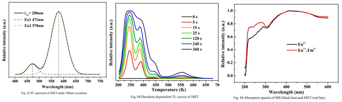
- Eu2+ at two different sites so two band shown in left figure.
- The time-dependent TL curves(middle figure), initially, TA is filled quicker than TB, but there is an opposite trend above 2 minutes. This suggests that TA primarily captures carriers until it is almost fully filled, and then it acts as a bridge to fill TB.
- The relevant absorption spectrum (right figure) of SSET(Eu,Tm codoping) exhibits increased absorption ability from 220 to 330 nm compared to that of SSE.
文献-6 Thermostability and photostability of Sr3SiO5:Eu2+ phosphors for white LED applications-JSSC-2015
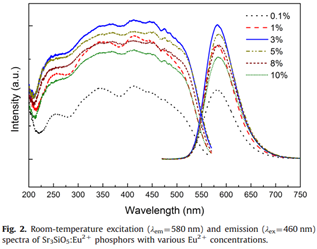
PLE and PL of Eu2+ doped phosphor (top-left figure), concentration of Eu2+ is optimized.
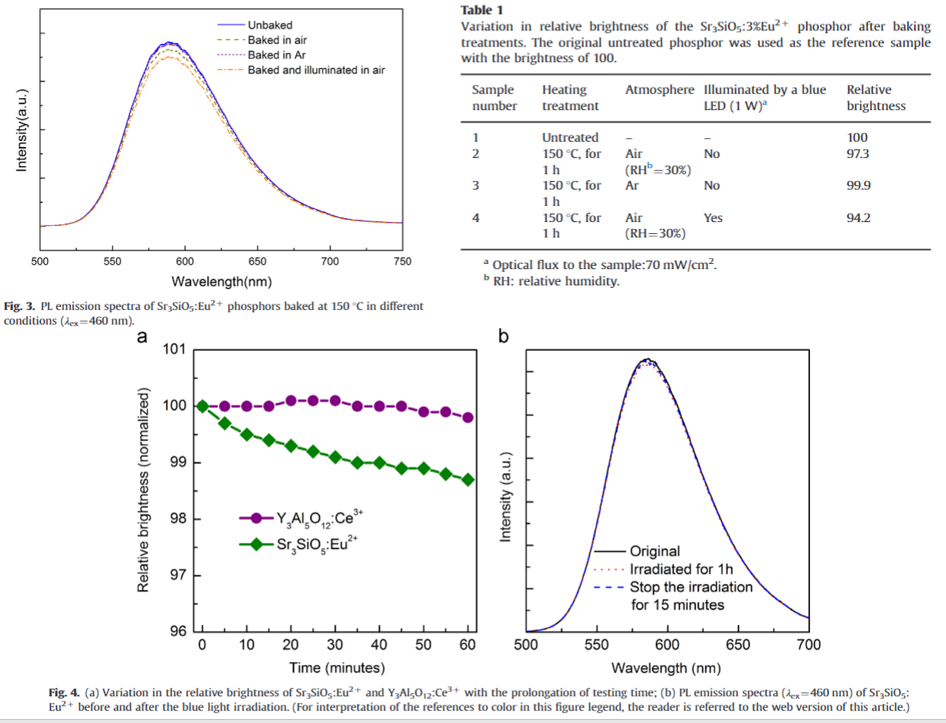
- Thermal degradation (two top figures): The decline in luminous output after treatment at higher temperature in air can be attributed to the degradation of the host lattice or the oxidation of Eu2+ ions in an oxidative atmosphere.
- Thermal degradation: Exposure to the blue light irradiation (460 nm) can aggravate the thermal degradation during the heating process.
- Thermal degradation: The photon energy of the blue light (460 nm) is lower that the band gap (Eg = 6 eV) , therefore blue light may not accelerate the degradation of host lattice. Instead, blue light can accelerate the oxidation of Eu2+ by promoting Eu2+ ions to higher-energy excited states (lower the activation energy of the oxidation of Eu2+ ions and acceleratetheir oxidizing process at higher temperatures.). (Figure 3)
- Photostability: (Figure 4a and 4b) It is measured at room temperature. YAG phosphor is used as well to be the reference. Under blue light irradiation (460 nm, 60 mW), Eu2+ emission shows the slight decrease (1.5 %).
- Photostability: At room temperature, the structure change of host lattice and the oxidation of Eu2+ ions are negligible, and the slight decrease of relative brightness may only be related to the continuous exposure to the blue light.
- Photostability: It is worth noting that this decrease in the relative brightness or emission intensity is reversible. After removing the light resource and keeping the phosphor in air for a period of time (20–30 min), the relative brightness can recover to 99.8 and the emission intensity can almost revert to the original value.
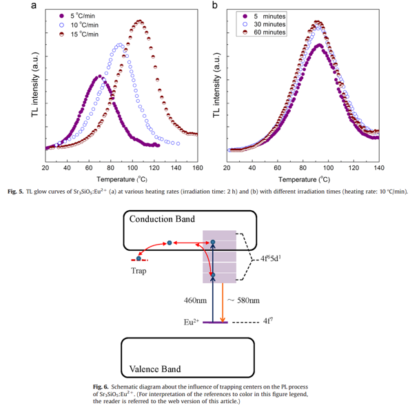
- The reversible variation in emission intensity during the blue light irradiation may be related to inherent traps.
- The trapping centers may originate from the oxygen vacancies that are formed during the phosphor preparing process in a reducing atmosphere.
- The ionization of Eu2+ ions and subsequent trapping are responsible for the photostability of the Sr3SiO5:Eu2+ phosphor.

- There are two nonequivalent Eu2+ sites. These two peaks are so close that only a single overlapped emission band is detected in the emission spectrum.
- The blue shift of Eu2+ emission with increasing temperature can be ascribed to back tunneling from excited states of the low-energy emission band to excited states of the high-energy emission band by assistance of thermally active phonons.
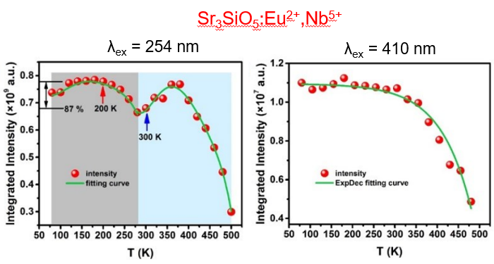
- At 150 oC, the integrated intensity of Sr3SiO5:Eu2+ can retain 92% of that at room temperature.
- Anomalous emission enhancement from 30 to 100 oC is related to trapping centers in the phosphor.
- Ba-substituted phosphors exhibit a more significant increase in the temperature range of 50–120 oC.
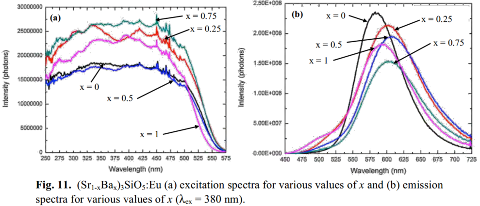
- With increasing Ba2+ contents emission peaks of Eu2+ ions shift to longer wavelengths and emission intensities are decreased. A rough estimation of Stokes shifts (SS) was made on the basis of the mirror-image relationship between excitation and emission spectra.
- Thermally assisted photoionization process rather than configuration coordinate model should be responsible for better thermal stability in Ba-substituted ones, according to the Stokes shifts results in different Ba-content. Because for configuration coordinate model, larger Stokes shifts results in smaller thermal barriers.
文献-7 [(Ba,Sr)3SiO5:Eu2+热稳定性-CEJ-五邑大学-2021]
这个也是固溶体?待补充

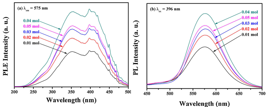
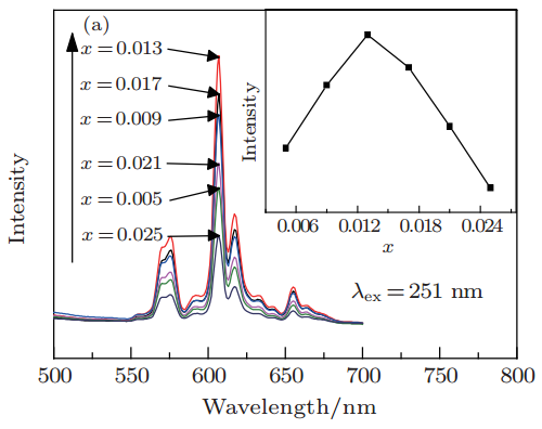
Another promising silicate phosphor was investigated: (Sr1-xBax)3SiO5,. Fig. 11(a) is the excitation spectra for various values of x, showing that the phosphor is efficiently excited from 370 nm - 412 nm. Additionally the spectra are flat in that region, indicating that small variations in the emission wavelength of the UV LED will not affect the intensity of the emission. The emission spectra (Fig. 11(b)) illustrate the peaks ranges from 580 to 612 nm depending on x. The QE of these phosphors are 85-95% at 0 ≤ x ≤ 0.5, 25-55% at 0.5 ≤ x ≤ 1.
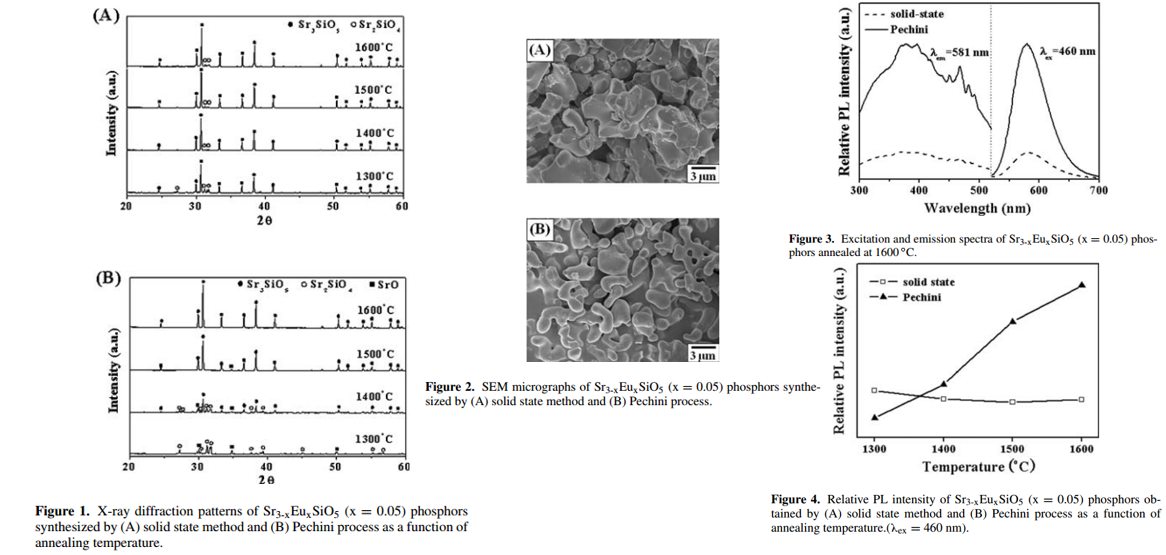
- Two methods were used to prepare Sr3SiO5, solid-state method and Pechini Process method.
- Solid-state method: The content of Sr2SiO4 gradually decreased with increasing the annealing temperature, but it was still detected in the sample annealed at 1600 oC. Thus, a single phase of Sr3SiO5 could not be realized by solid-state reaction method.
- Pechini Process method: At 1600 oC, a single phase of Sr3SiO5 was obtained.
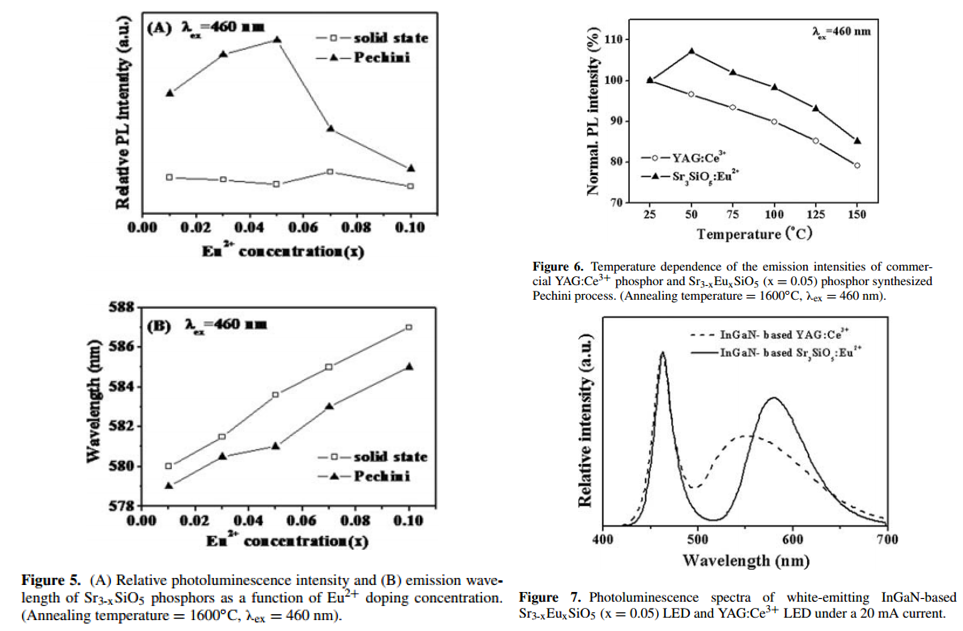
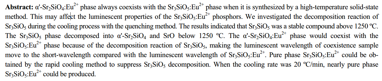
- Many experimental results showed that particles with a uniform shape and a smooth surface had better luminescence intensity than particles with an irregular shape and a rough surface. Thus, the powder synthesized by Pechini process is expected to have a higher PL intensity, which is confirmed in Figure 3 and Figure 4.
- The effects of Eu2+ doping concentration on the PL intensity and wavelength are shown in Fig. 5.
- * The emission peak was continuously shifted to a longer wavelength with increasing Eu content, which is related to the re-absorption of emitted light.
- There was a slight increase of emission intensity at 50 oC. This is also reported in Application of strontium silicate yellow phosphor for white light-emitting diodes-2004-APL, but the reason is not well understood at this stage.
- Sr3-xEuxSiO5 phosphor is superior to commercial YAG:Ce3+ phosphor in terms of thermal stability.
文献-10 Synthesis of Sr3SiO5:Eu2+ Yellow-orange Phosphor by Gelation Method Using Propylene Glycol-Modified Silane
Main content: Optimzation of preparation to get pure phase, PL and PLE are not shown in this paper.
文献-11 Influences of phase composition on Sr3SiO5:Eu2+ luminous performance
文献-12 Enhancement of luminescence and thermal stability in Sr2.92-xTmxSiO5:Eu2+ for white LEDs
- 5d electron state of Eu2+ which easily influenced by the crystal field was not changed after Tm3+ co-doping in the host.
- Enhanced emission intensity, improved thermalstability and fluorencence decay time have been made via crystal chemical unequivalence substitution of Tm3+ in Sr2+ site.
- Jieqi: Actually, the discussion on energy transfer between Eu2+ and Tm3+ by the author is not convincing.
文献-13 The influence of BaF2 flux concentration on the luminescence of Sr3SiO5:Eu2+
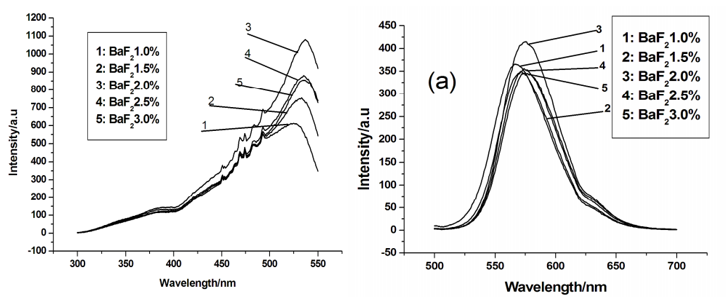
- The impurity structure disappears when the BaF2 concentration is 2.0wt%.
- Emission peak position and intensity change a little with differrent BaF2.
文献-14 Synthesis and Luminescence Properties of Eu2+-activated Sr3SiO5 Phosphors
- Sr3SiO5 formed at 1400 oC. At 1300 oC, main XRD peaks are related to Sr2SiO4 and SrO.
- Remarkable enhancement in luminescence characteristics was observed when fumed silica was used. This phenomenon may be attributed to the improvement of Eu2+ dispersion in Sr3SiO5 phosphors.
- When small sized silica powder was used, the resulting Sr3SiO5:Eu2+ particles grew and became larger quickly.
文献-15 Luminescence Property of Eu2+ Doped Strontium Silicate Yellow Phosphor for White Light Emitting Diode
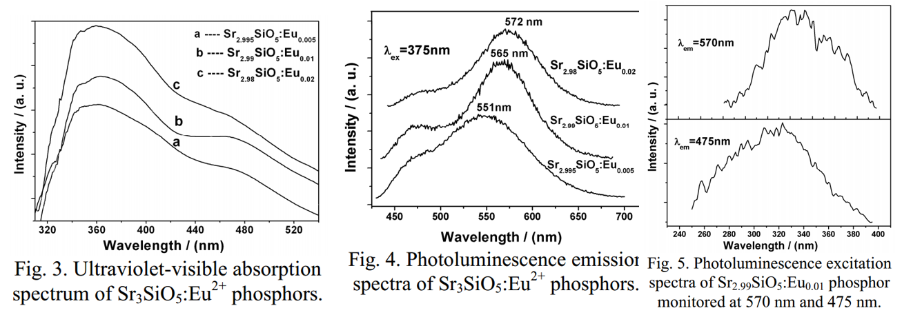
- Two emission bands corresponding to Eu2+ in different sites.
- Impurity Sr2SiO4 exists.
- Absorption spectra are shown above.
文献-16 Synthesis and luminescence property of Sr3SiO5:Eu2+ phosphors for white LED

- Flux has an influence on both peaking position of PL band and PL intensity.
- The reason for band shift is not given in this paper.
- Microwave-assisted sintering.
- Actually, impurity Sr2SiO4 shown in XRD, which is ignored by the author.
文献-18 PhotoluminescenceProperties of Sulfur-doped Sr3SiO5:Eu2+ Phosphor for White LEDs
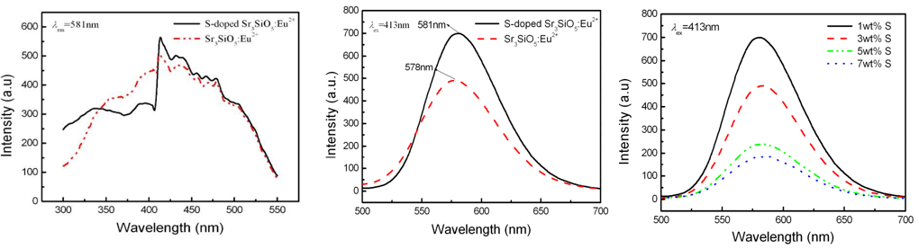
- Actually, impurity Sr2SiO4 shown in XRD, which is ignored by the author.
- Influence of S on PLE and PL.
文献-19 Effects of the Sr/Si Ratio on the Photoluminescence Properties of Sr3SiO5:Eu2+ nanophosphors
- Phosphors were synthesized by sol–gel method.
- Actually, impurity Sr2SiO4 shown in XRD, which is ignored by the author.
- PL intensity can be improved by changing the ratio of Sr/Si.
文献-20 Luminescence investigations of Sr3SiO5:Eu2+ orange–yellow phosphor for UV-based white LED

- Sr3SiO5 prepared at different temperatures and different Eu concentrations.
- The author said that energy transfer occurs at different Eu2+ site in Sr3SiO5. (one site 480 nm, the other one 566 nm emission)
- Very small content of Impurity of Sr2SiO4.
文献-21 Synthesis and Photoluminescence Propertiesof Sr3SiO5:Eu2+, Mn2+

- Sr3SiO5 prepared at different temperatures and different Eu concentrations.
- The impurity Sr2SiO4 still obvious at optimal temperature (1600 degree).
- PL and PLE are shown.
- As is shown in this paper, I think the influence of coping with Mn2+ is negligible.
文献-22 Photoluminescence properties of Eu2+-activated Sr3SiO5 phosphors
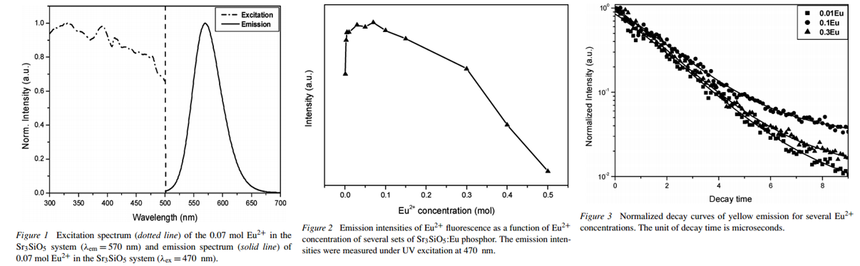
In summary, the author have synthesized a Eu2+-doped Sr3SiO5 yellow phosphor, and investigated its photoluminescence properties. The emission band of the Sr3SiO5:Eu phosphor is observed and this phosphor emits efficiently under the 450–470 nm excitation range. The critical distance value of energy transfer between Eu2+ ions and the electric multipolar character were obtained experimentally from the decay fitting results.
文献-23 Embodiment and luminescence properties of Sr3SiO5:Eu(yellow-orange phosphor) by co-doping lanthanide
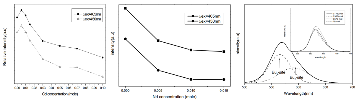
- Codoping with Gd, increases Eu2+ PL a little bit, while codoping with Dy, Ce, Pr decreases Eu2+ PL intenisty.
- PL band is not symmetrical for Nd3+ codoped sample, which can be attributed to two kinds of Eu2+ sites.
文献-24 Si3N4 掺杂氮化对 Sr3SiO5:Eu2+荧光粉发光性能的影响
与 YAG:Ce3+荧光粉相比, 硅酸盐荧 光粉光谱范围更宽, 在紫外、近紫外或蓝光的激发 下能够表现出多种发射光颜色。在正硅酸盐中, 以 Eu2+离子或 Ce3+离子激发的 M2SiO4、 Li2SrSiO4、 Sr3SiO5荧光粉最具研究价值和应用潜力。Sr2.99SiO5-6xN4x:0.01Eu2+。适量掺杂 N3-离子可以 提高 Sr2.99SiO5:0.01Eu2+荧光粉的热稳定性。这是因 为 Si–(O, N)键共价性比 Si–O 键要强, 掺杂 N3–离子 后可以提高荧光粉基质晶格结构的稳定性。
文献-25 Tunable Emission Color and Mixed Valence State via the Modified
Activator Site in AlN-Doped Sr3SiO5:Eu Phosphor-RSC advances-2016
待补充
文献-26 Energy transfer between activators at different crystallographic sites in Sr3SiO5:Eu2+
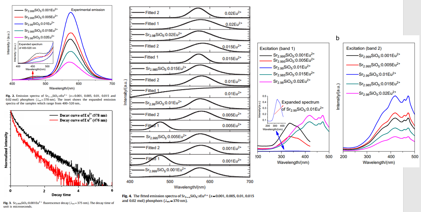
- Pure Sr3SiO5 by solid-state reaction.
- When Eu2+ concentration is rather low, two centers emit light and form respective emission bands at 476 (Eu1) and 578 nm (Eu2).
- When doping concentration is more than 0.01 mol, only the yellow emission band is observed.
- Lifetime measurement confirms two kinds of Eu2+.
- PLE measurement confirms two kinds of Eu2+
- The energy transfer mechanism is the dipole–dipole interaction.
Eu2+闪烁特性
文献-1 Combinatorial Screening of Advanced Scintillators for High Resolution X-ray Detectors
Eu2+ PersL or OSL
- Only the electrons excited by UV can be effectively captured by traps responsible for phosphorescence. (Figure 2b)
- Each of the two decay patterns consists of a fast decay and a consequent slow decay with a long decay tail, implying the existence of various trap depths. (Figure 4)
- Trap A and B contribute to the slow decay component. Traps for fast decay component is too quick to be measured by TL results here. (Figure 5)
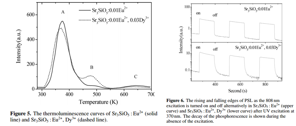
- By co-doping Dy3+, Trap B peak is remarkably enhanced, thus increasing PersL time. (Figure 5)
- By co-doping Dy3+, calculated trap depth shifts from 0.66 eV to 0.85 eV, in other words, more shallow traps. (Figure 5)
- For OSL/PSL results, Dy3+ codoped sample shows slow rising and falling edges, which can be explained by efficient retrapping process under 808 nm stimulation due to the existence of a large number of shallow traps. ?
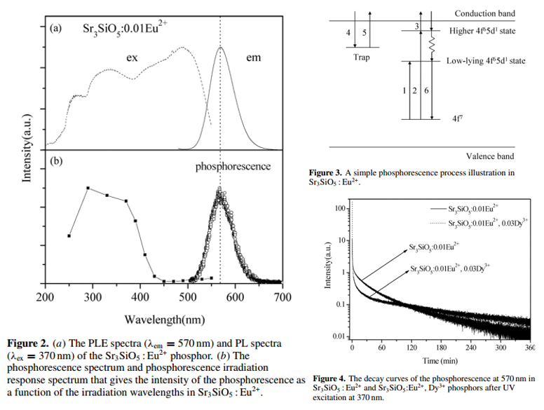
文献-2 Effect of retrapping on photostimulated luminescence in Sr3SiO5:Eu2+, Dy3+ phosphor-JAP-2009
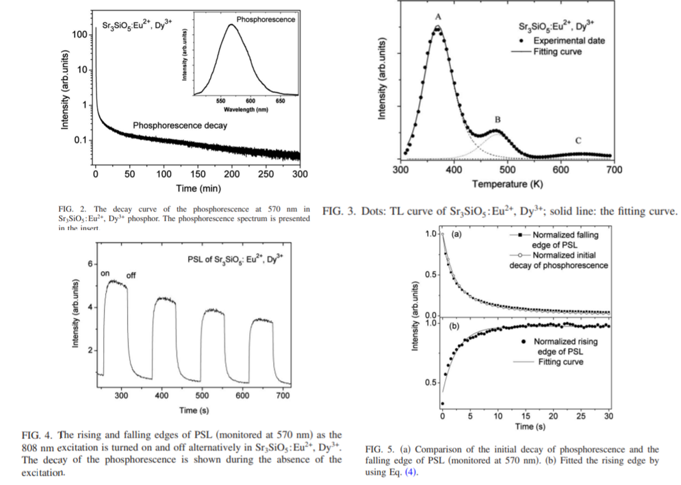
- The decay pattern obviously consists of a fast component in the initial period of several seconds and a subsequently slow component as well as a very long decay tail after 1 h. (Figure 2)
- Trap C, is not considered to be thermally released at room temperature. (Figure 3)
- The slow phosphorescent component and the long tail are mainly attributed to the contribution of traps A and B, respectively. (Figure 3)
- For the fast phosphorescent component, the responsible TL peak is not recorded in Fig. 3 because the fast component lasts only several seconds at room temperature. (Figure 3)
- By TL fitting, traps A, B, and C to be 0.60, 0.80, and 1.09 eV, respectively. (Figure 3)
- The obtained order of kinetics for traps A, B, and C are 2, 1.29, and 2, respectively, indicating the existence of retrapping. (Figure 3)
- The strong orange PSL is observed under 808 nm excitation.
- PSL dose not cease promptly, but lasts several seconds after the termination of the infrared stimulation. This can be explained by retrapping. (Figure 4)
- Slow rising edge of PSL is presented after turning on the infrared stimulation, which can be explained by recharging of the shallow traps (retrapping) . (Figure 5)
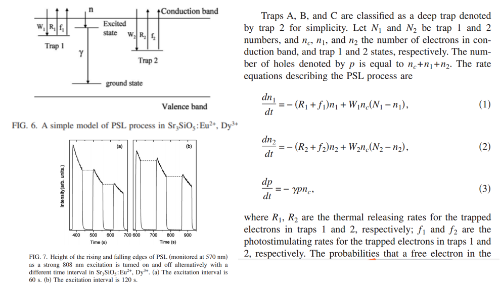
- A simple model of PSL process is proposed to simulate the rising and falling edges of the PSL. (Figure 6)
- The rising edge is higher than the former falling edge. The results imply that the process of retrapping by deeper traps also occurs in the decay period of thermally activated phosphorescence stored in the shallower traps. (Figure 7)
- All in all, during PSL, retrapping by shallow traps occurs; after the cease of PSL, retrapping by deep traps occurs.
- PSL could be used as a probe to study retrapping process in phosphorescent materials.
文献-3
(1) Persistent Luminescence from Sr3SiO5:Eu2+ by R3+ Co-Doping: An X-Ray Absorption Study
(2) Yellow Persistent Luminescence of the Sr3SiO5:Eu2+,R3+ Materials
(3) Efeito dos íons terras raras trivalentes (TR3+) como co-dopantes na persistência luminescente do Sr3SiO5:Eu2+,TR3+
These are three very short reports/abstracts (not papers) by the author Jorma Hölsä in University of Turku. No corresponding formal papers can be found.
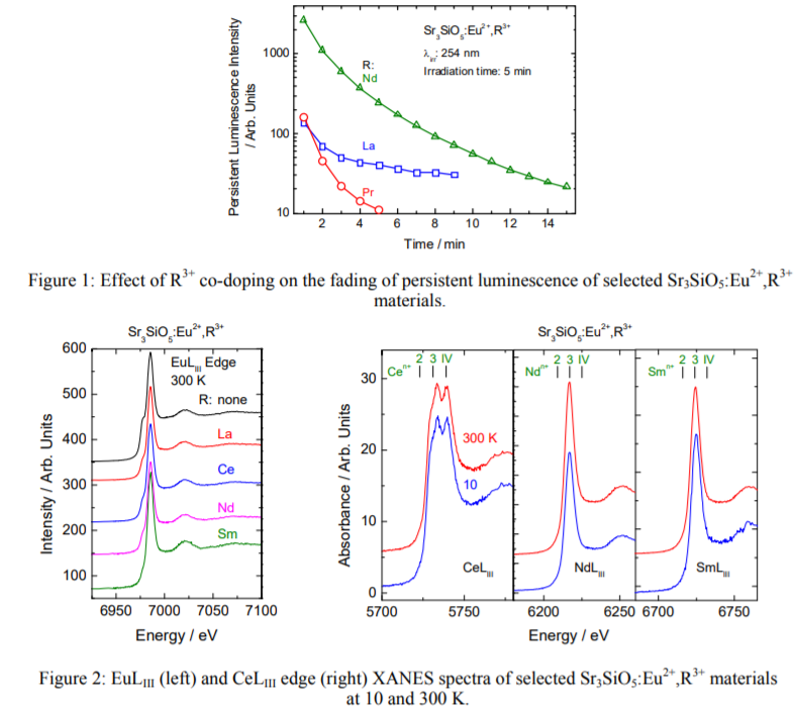
Main content: (First-report)
- A small amount of a Sr2SiO4 impurity exists in Sr3SiO5 according to XRD result.
- Besides Eu2+ yellow band (577 nm), 480 nm band is also shown in PL.
- Co-doping weakens 577 nm band, while enhences 480 nm band.
- La, Ce, Pr, Nd, Gd, Dy, and Tm codoped phosphor show PersL. Nd3+ is the best co-dopant.
- XANES results at both room temperature and 10 K show a clear dominance of the trivalent form over the divalent one for all materials studied, which contradicts the results obtained by luminescence of main emitter Eu2+.
- Strong Eu3+ XANES signal probably comes from charging process (like SrAl2O4:Eu2+,Dy3+), Eu2+ oxidation in the X-ray beam.
- For Nd and Sm sample, no Eu2+ XANES signal.
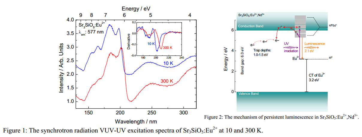
Main content: (Second-report)
- 202 nm (6.14 eV) is related to bandgap transition.
- Bandgap transition shows redshift at 300 K when compared with 10 K result.
- Strongest persistent luminescence was obtained with the xEu/xR ratios of 0.01/0.01 and 0.001/0.01 for the Nd3+ and Dy3+ co-doped materials, respectively.
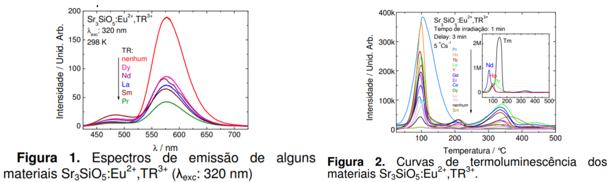
Main content (Third-report): Already shown above (Two figures).
文献-4 Strongly enhancing photostimulated luminescence by doping Tm3+ in Sr3SiO5:Eu2+-OL-2013
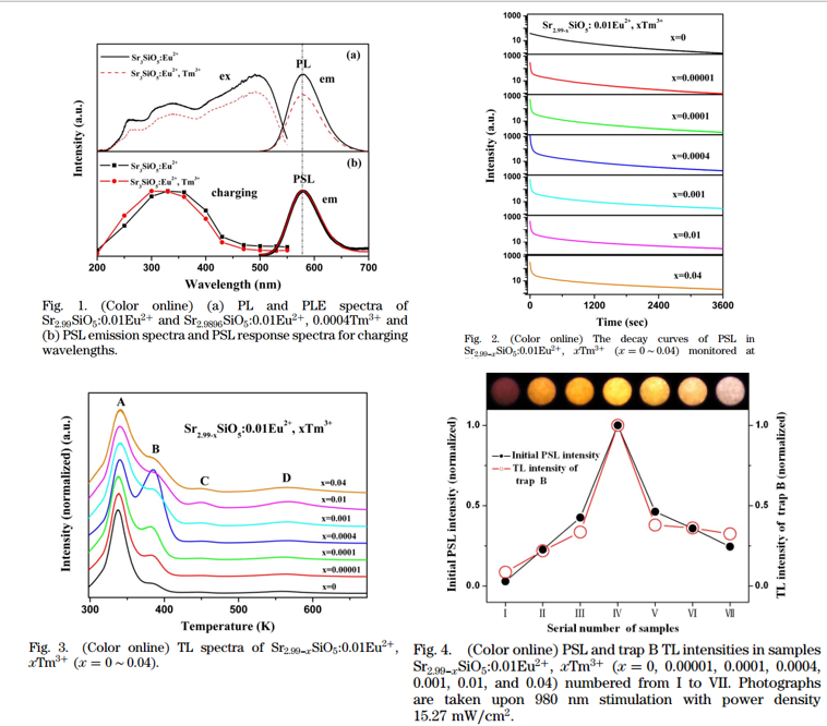
- PSL(OSL, 980 nm laser ) charging spectra indicate that only UV light can be stored. (Figure 1b)
- Trap type could be electron trap. Because if trap type is hole trap, PLE and PSL charging spectra should be identical. In other words, for hole traps, charging should not be influenced by the electrons either in higher or the lowest lying excited states of Eu2+.
- Initial PSL intensities enhance strongly as Tm3+ is codoped.
- Tm3+ induced PSL exhibits a very fast decay compared to the original one.
- The enhancement of PSL is correlated to the generation of trap B. (Figure 4)
- The origin of trap B is still unclear at present.
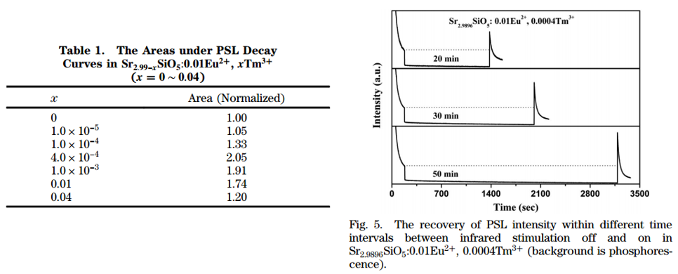
- Total photons emitted in PSL refer to the light storage capacity. The maximum area also occurs at x = 0.0004, with the value twice that for the Tm3+-free sample.
- As the stimulation turns on again, the PSL intensity becomes stronger than that at the time stimulation was off. (Figure 5)
- With increasing the time interval between stimulation off and on, the recovered PSL enhances. (Figure 5) This can be explained by the retrapping from trap A (released by thermal energy at RT) to trap B (released by 980 nm stiumlation, not by thermal energy at RT) through conduction band during interval time.
- Among all R3+ codopants, only Tm3+ shows remarkable production of a new trap B and the enhancement of PSL. The reason is still unclear at present.
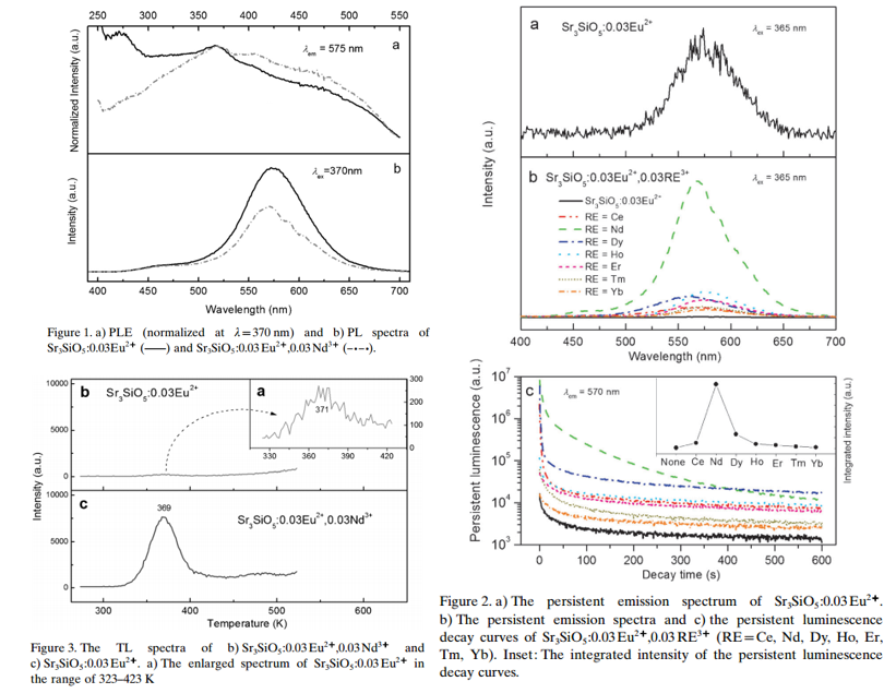
- The introduction of Nd3+ ions decreases the emission intensity of Eu2+. (Figure 1b)
- For single Eu2+ doped sample, the persistent spectrum is very weak, and the introduction of other Ln3+ can increases the persistent spectra intensity. (Figure 2)
- The irradiation source is a mercury lamp that peaked at 254 nm (5 min) in this paper.
- TL (peak 371 K) for single Eu2+ doped sample is very weak. (Figure 3)
- General-order TL kinetic expression is used to fit th TL curve of Nd3+-codoped sample, the calculated trap depth is 0.94 eV.
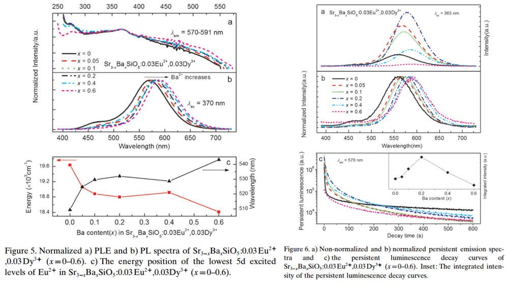
- Ba2+ is introduced to the Eu2+-Dy3+ codoped sample, PL peak shows red shift.
- The introduction of Ba2+ also increases the TL intensity, optimal Ba-content is 0.2.
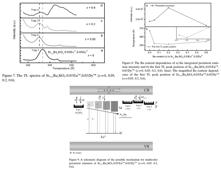
Main content: (Sr3-xBaxSiO5:0.03Eu2+,0.03Dy3+)
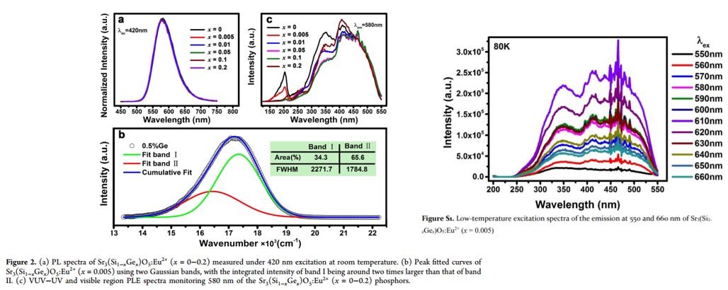
- The TL properties strongly depend on the amount of Ba ion present for Sr3-xBaxSiO5:0.03Eu2+,0.03Dy3+. (Figure 7)
- More shallow trap appear after the introduction of Ba2+.
- For 0.2 Ba2+ sample, trap depth is 0.65 eV. (trap 2)
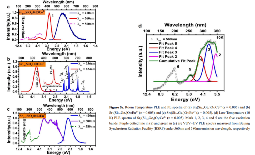
文献-6 Enhanced Yellow Persistent Luminescence in Sr3SiO5:Eu2+ through Ge Incorporation-IC-2019
- Chemical coprecipitation combined with a solid-state reaction method is used to prepare samples.
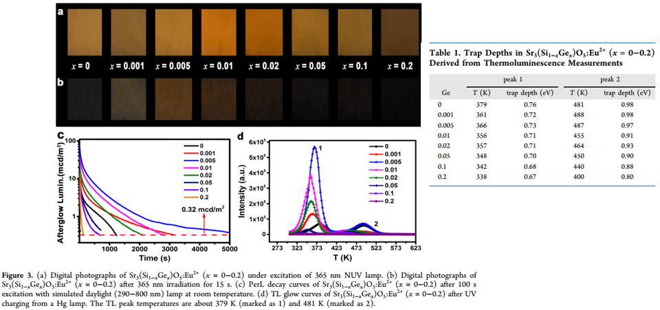
- Two Gaussian bands can be related to Eu2+ ions in two different Sr2+ sites.
- Excitation spectra at 80 K for two kinds of Eu2+ show that there is no obvious relative shift between the onsets. (Figure S1)
- DFT formation energy calculation confirms Eu2+ occupations at the two Sr sites are almost equally stable.
- The excitation band at ∼200 nm is attributed to the host excitonic absorption, from which the host band gap is estimated to be 6.68 eV after taking into account the electron−hole binding energy of the exciton.
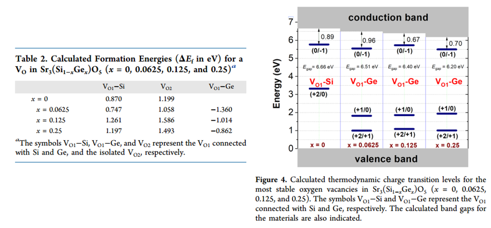
- For persistent luminescence measurement, 100 s excitation with a simulated daylight (290−800 nm) lamp is adopted.
- 0.005Ge sample shows the bets PersL performance. (blue line in Figure 3)
- Trap depth is calculated by ET = T/500 eV. (Table 1)
- The trap depth shows a gradual decrease with increasing Ge-content.
- DFT formation energy for oxygen vacancy is calculated to explain the dependence of TL performance on Ge-content.
- The results of calculated thermodynamic charge transition levels, is consistent of TL trap depth (peak-1). (Figure 4)

- Bandgap Evc is 6.64 eV.
- Different excitation wavelengths only change the relative intensities of the peaks, indicating same type traps. (Figure 5a)
- Electrons excited directly from the 4f7 ground state of Eu2+ to the higher 5d levels closed or submerged in the conduction band mostly contribute to the persistent luminescence. (Figure 5b)

Main content: VRBE, and PerSL mechanism.
Main content: PL and PLE for Ce3+, Eu3+, Eu2+ doped samples. The results are used to construct VRBE.
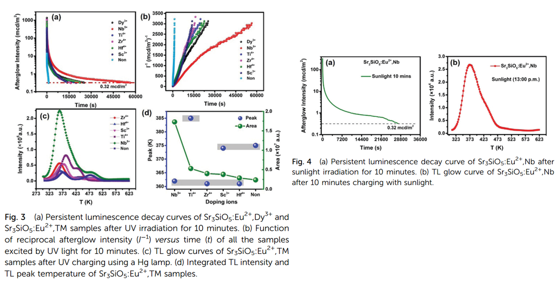
- Different TM ions are used to imporove PerSL performance. Nd3+ is the best one.
- Sr3SiO5:Eu2+, Nd shows sunlight-activated persistent luminescence. More than 7 hours. (Figure 4)
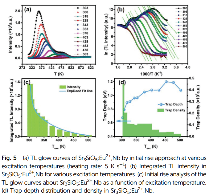
- By initial rise analysis, Figure 5d shows that upon excitation at room temperature, the estimated trap depth is 0.67 eV.
- It is interesting to observe that the density of the traps with depths ranging from 0.79 eV to 1.05 eV remains at a high level. This could be one of the reasons for the long persistent luminescence time.

- TL under different excitation wavelength 230–500 nm, same TL peak position, suggesting same type traps. (Figure 6a)
- TLE spectrum shows TL intensity depends on excitation wavelength, 250–380 nm irradiation is suitbale for TL. (Figure 6b)
- By comparing PLE and TLE, it is resonable that traps could not be efficiently charged by electrons excited from the 4f ground state to lower 5d levels of Eu2+. (Figure 6b)
- 3D-TL curves confirms emission center Eu2+ during heating. (Figure 6c)
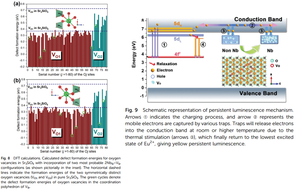
- DFT calcuation shows that by co-doping Nb, more oxygen vacancies are obtained. Because Nb introduces Sr vacancy, which is crucial to diminish the formation energies for oxygen vacancies. (Figure 8)
- PerSL mechanism. (Figure 9)
文献-8 Orange super-long persistent luminescent materials: (Sr1−xBax)3SiO5:Eu2+,Nb5+-Mater. Chem. Front., 2021
xxxxx
文献-9 Enhancement of yellow emission and afterglow in Sr3SiO5:Eu2+, Dy3+ by adding alkaline earth metal fluorides
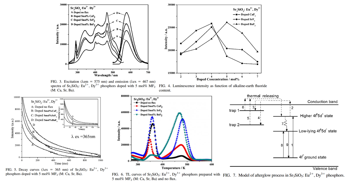
- There is a structure transformation from Sr3SiO5 to Sr2SiO4 at 1300 °C in the process of the reaction and Sr2SiO4 phase forms below 1300 °C. The rapid cooling treatment can prevent the transformation effectively and thus improve the impurity of the final product (From XRD results).
- Flux CaF2 / SrF2 /BaF2 contributes to the formation of Sr3SiO5 pahse, even though Sr2SiO4 still exists.
- With the introduction of MF2, the initial afterglow intensity increases and the afterglow decays more slowly.
- The relative densities of the traps at different depths change obviously with the addition of MF2.
- It is noted that though the long afterglow can be observed under UV excitation, the initial afterglow intensity becomes very weak and the afterglow also decays quickly when the phosphor is excited at 411 nm.
- While excited at 467 nm, the luminescence can be obtained but no afterglow is observed.
文献-10 Crystal Structure Induced Enhanced Afterglow Luminescence from Rare-Earth Ion Doped Strontium Silicate Phosphors

- Zn2+ is introduced to increase PL intensity.
- The enhanced afterglow property of >20 minutes has been achieved for dark-adapted human eyes.
- (Jieqi) It should be mentioned that PL peak locates at 610 nm, which is different from other papers. The impurity phase is ignored by the author.
Ce3+ PL and PersL

- Sr3SiO5:Ce3+, Li+ shows high luminous efficiency under near-UV light as well as under blue light, and emission from this phosphor is broad.
- Sr3SiO5:Ce3+, Li+ is a promising phosphor applicable to near-UV LEDs as well as blue LEDs.
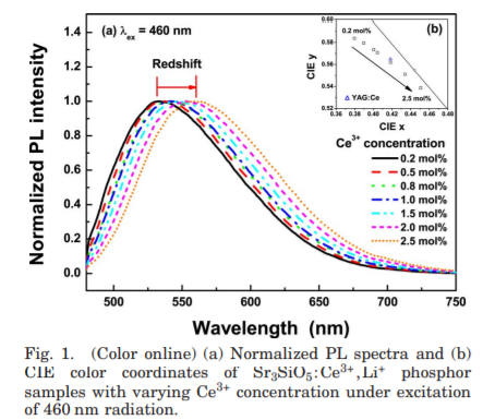
- With an increase of the peak wavelength of the Ce3+ emission, the body color of the phosphor changed from greenish-yellow to yellow. In addition, a redshift in the color coordinates of the Sr3SiO5:Ce3+,Li+ samples occurred.
- According to Setlur and Srivastava the color shift at higher Ce3+ concentrations is primarily due to inhomogeneous broadening of the Ce3+ emission band leading to energy transfer between intrinsic higher energy Ce3+ sites and lower energy Ce3+ sites.
- LED fabrication.
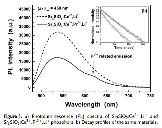
- The incorpration of Pr3+ is to increase the red emission component. However Pr3+ emission is very weak.
- Therefore, the author combined QDs and Sr3SiO5:Ce3+,Li+ Phosphors together to fabricate LEDs.

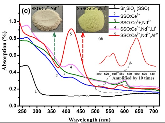
- XRD of Sr3SiO5:Ce3+ with/without different addition. Only sample with Al2O3 addition is pure phase (not Sr2SiO4 XRD peaks). (up left). The introduction of Al3+ ions have the capacity to optimize the crystallinity degree of Sr3SiO5
- The addition of B3+, Ga3+ and Al3+ increases Ce3+ PL intensity. Al3+ co-doped one shows the optimal PL. (Figure 4)
- PL intensity with different Al3+ concentration is investigated. (Figure 5)
- PL intensity with different Al3+-Ce3+ concentration is investigated. (Figure 6)
- dipole–dipole interaction is the concentration quenching mechanism of Ce3+ (inset of low right)
- Rc critical distance for energy transfer is calculated for Ce3+.
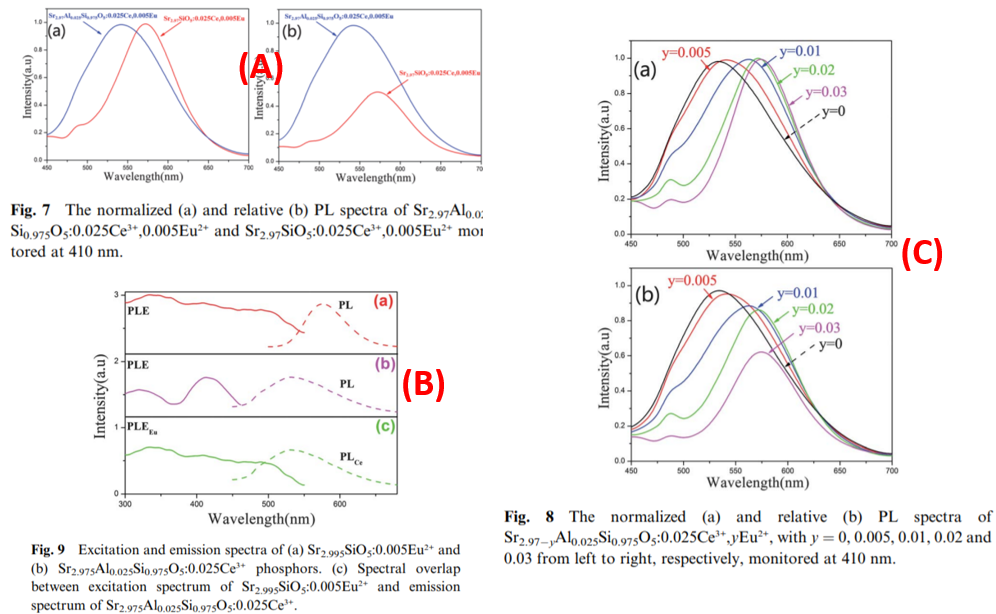
- For Ce3+ Eu2+ codoped sample, the addition of Al3+ influence PL intensity and emission color. (Figure A)
- Eu2+ doped, Ce3+ doped, Ce3+-Eu2+ codoped samples shows necessary overlap for energy transfer. (Figure B)
- Different Eu2+ concentration, different situation for energy transfer between Ce3+ and Eu2+, color tunable PL. (Figure C)
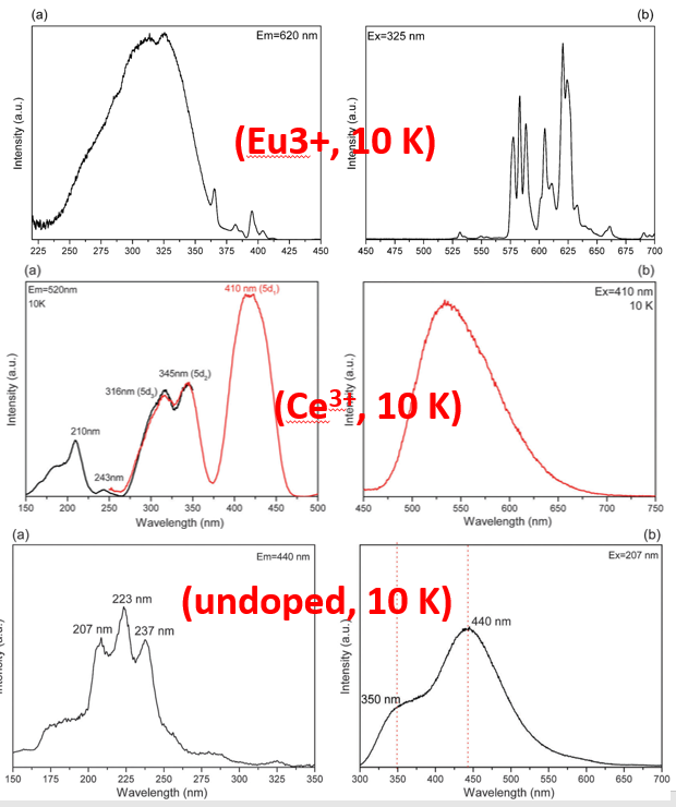
- Undoped sample, PLE is attributed to host exciton creation (207 nm) or unknown defects ((237–243 nm)).
- O2- to Eu3+ CT band at 320 nm.
- Anomalous yellow emission of Ce3+ is due to the combination of a large crystal field splitting and Stokes shift according to the result of VRBE (vacuum referred binding energy ) scheme.
- The ground states of divalent Nd, Sm, Eu, Dy, Ho, Tm and Yb are below the conduction band, which indicates that the corresponding trivalent ions can work as electron traps.
- Temperature dependent lifetime of Ce3+ is measured, the measured thermal energy is different from the energy (according to VRBE) of thermal ionziation to the conduction band or via an impurity trapped exciton state. Therefore, thermal quenching of Ce3+ is also due to crossing point in the configuration coordinate diagram.
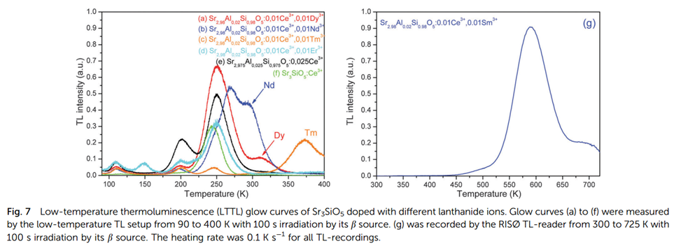
- TL is measured after irradiation by β source, also for the subsequent results if not specified.
- TL peak at 250 K is attributed to a host defect.
- TL peak at 200 K is attributed to charge compensator Al3+.
- The additional glow peaks observed in the Dy, Tm, Sm, and Nd, co-doped samples are attributed to the release of electrons trapped in the lanthanide.
- To get a more reliable value for Tm (Randall-Wilkins method), TL is measured after thermal peak cleaning, and the final Tm for trap depth of Nd3+, Dy3+, Tm3+ and Sm3+ is calculated to be 0.90 eV, 0.95 eV, 1.15 eV and 1.83 eV, respectively.
- Dy3+ codoped sample shows the best PerSL decay spectra due to suitable trap depth (Figure is not shown here).
- No TL glow peaks were observed related to Yb in the Yb co-doped samples, which can be explained by deeper traps and severe thermal quenching at that high temperature to relase filled traps.
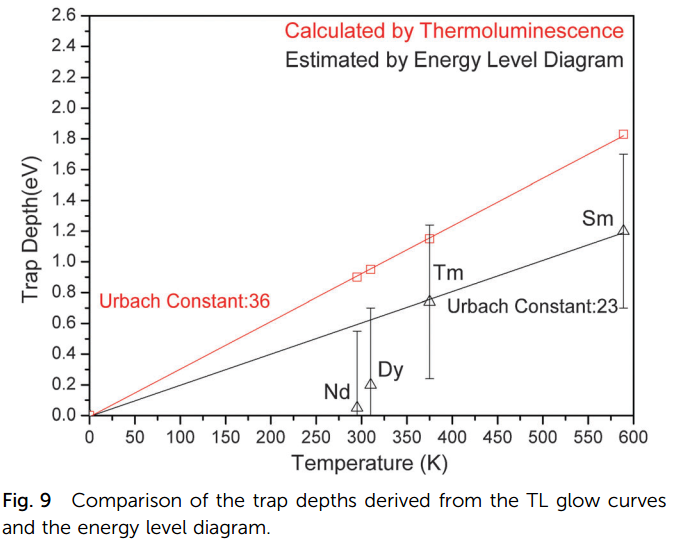
- Measured Tm versus calculated Trap depth can be well-fitted by a linear function with Urbach constant.
- Measured Tm versus Trap depth from VRBE is also fitted.
- The difference between red results and black results can be explained by the uncertainty of TL exeriments.
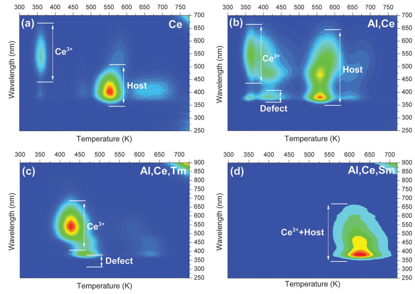
- TL emission (TLEM) spectra above room temperature have been recorded to establish the nature of the hole trapping and recombination center.
- No emission from Tm3+ or Sm3+ is monitored, which means that Tm3+ and Sm3+ do not work as recombination centers.
- Ce3+ or host defects related emission is observed.

- Thermoluminescence excitation (TLE) spectra for Ce3+ and Dy3+ codoped sample, a Xe lamp.
- Sample is excited by a Xe lamp.
- There is no TL response of the sample when the wavelength is longer than 400 nm, which can be explained by the large energy difference 5d1 excited state and conduction band.
- TLE peak at 350 nm is consistent with PLE spectra.
- TLE peak at 260 nm is not observed in PLE spectra, which is assigned to unknown charging defect. Charging might be via its excited state located within the conduction band or via a direct transition from its ground state to the CB.
- Right figure displays the TL spectra after 260 nm illumination at different temperature. Peak I relates to Ce3+ emission and peak II to host emission.
文献-6 Preparation and Application of Strong Near-Infrared Emission Phosphor Sr3SiO5:Ce3+,Al3+,Nd3+
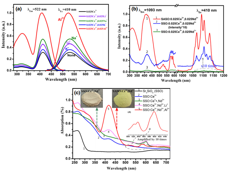
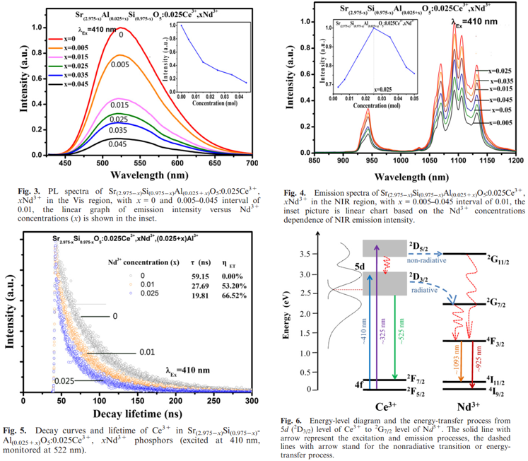
- The idea of this paper is that Al3+ ions have the ability to promote Ce3+ ions to enter into the Sr2+ sites and to improve the visible emission of Ce3+. This phosphor can be used as spectral convertors to improve the efficiency of c-Si solar cell.
- Energy-transfer efficiency can be obtained by lifetime. The efficiency is 66.52% when the concentration of Nd3+ is the most optimal.
Cs3CoCl5家族
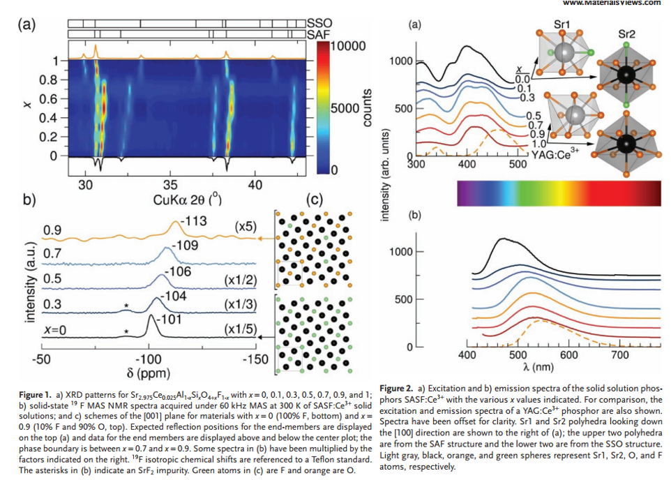
- Sr3AlO4F (SAF, space group P4/ncc) and Sr3SiO5 (SSO, space group I4/mcm) are nearly isostructural.
- SAF can withstand more strain and distortions than SSO. (Figure 1a)
- Increasing SSO content in SASF:Ce3+ improves moisture stability, which is indicated by the content of SrF2. (Figure 1b)
- Color-tunable for PL and PLE in SAF-SSO soild solutions. (Figure 2ab)
- The solid-solution phosphors have wider emission peaks than SAF:Ce3+, good for CRI. (Figure 2b)
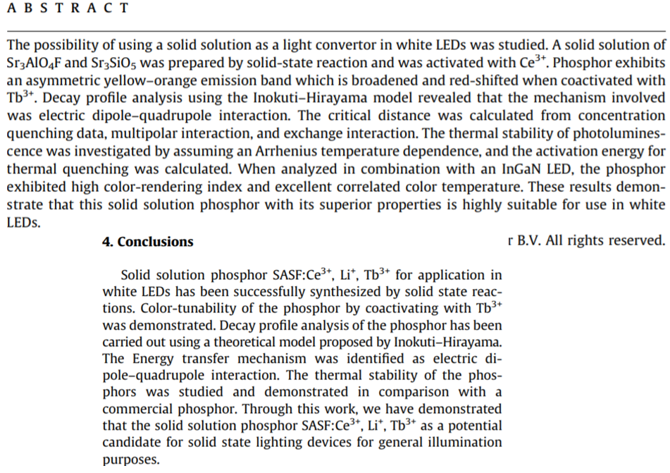
Jieqi: No special conclusion. So I just copy and past the parts of ABSTRACT and Conclusion
文献-2 Insight into the preparation and luminescence properties of yellow-green-emitting [(Sr,Ba)3AlO4F–Sr3SiO5]:Ce3+ solid solution phosphors-2017
- Two step methods for the synthesis.
- It was found that enhanced emission intensities could be obtained using the two-step method with high crystalline quality.
- The emission peaks of the (1 − x)Sr3SiO5–x(Sr,Ba)3AlO4F:Ce3+ phosphors were blue-shifted from 520 to 490 nm upon increasing the content from x = 0 to x = 1.0.
- The formation of a solid solution can improve the thermal stability.
Other single Ln3+ doped ones
文献-1 Effects of Li+ on photoluminescence of Sr3SiO5: Sm3+ red phosphor
- doping codoping with Li+ impprove PL and suppress the concentration quenching of Sm3+.
- No PLE of Sm3+ is given in this paper. Eu3+ PL and PLE can be found in previously discussed paper Enhanced Yellow Persistent Luminescence in Sr3SiO5:Eu2+ through Ge Incorporation-IC-2019